 |
| Schematic Wiring Diagram of oxygen sensor circuit. The above diagram shows the different links to the inputs and outputs of each operational-amplifier from the power source and how each operation amplifier is wired to operate each seperate light emitting diode. Also shows calculations to obtaining each resistor value which is shown in previous blog. |
 |
| In this diagram shows a DC (direct current) power supply. The above equipment was used to to supply voltage to the sensor input of the oxygen sensor circuit. This was used to test the oxygen sensor circuit by turning one of the dials on the machine which would send different votage signals to the sensor input, depending on the amount of voltage you turned the DC power supply would determine which circuit of the oxygen sensor would operate. This machine was used to simulate the throttle of a vehicle. the higher you turned the dial would simulate you putting your foot down on the accelerator. How it Works? Starting with a 12 volt power supply voltage flows through the diode which leaves available vlotage of 11.4 as it causes a 0.6 voltage drop to the resistor (r5) to the 9.1volt zener diode and capacitor. the capacitors are put in the circuit to prevent voltage surges and to keep a steady voltage flow. Also from the power supply, after diode it has a connection to the op-amp before the resistor (r5) to pin 4 of the op-amp, that is known as the positive voltage rain of the op-amp. From the zener diode it voltage flows to the next resistor (r6) but because of the zener thier is only 9.1volts availabe. after the resistor it breaks off to pin 2 of the first op-amp and then pin 5 of the second op-amp, and because of the resistance put in the circuit we have 0.63 volts available at both pin 2 and pin 5. In a straight connection after r6 and after pin 2 and pin 5 inputs voltage flows to the next resistor (r8) which then connects to pin 10 of the third op-amp and pin 13 of the fourth op-amp, and again because of adding the resistance created a 0.4voltage drop so at pin 10 and pin 13 has available voltage of 0.23 volts. From r8 it goes to another resistor in the circuit r7 which goes to ground. The op-amp has a negative volt rail which is pin 11 and is connected to earth. Each op-amp has an output, those pins are numbered as pins 1,7,8 and 14. pins 7,8 and 14 each connect to and individual LED which has a positive feed from the 12volt power supply after the diode which leaves 11.6 volts available to each LED, but at pin 8 from the anode side of the LED has a another diode. Between the LED and output pins 7,8 and 14 have resistors r2,r3 and r4. The output pin1 has and diode connected to it which connects to pin 8 in between the resistor and LED on the cathode side of the LED. Each LED with the power supply on is hot at all times. Input pins 3,6,9 and 12 are connected in parallel and are the sensor inputs. |
 |
| When sensor input is at zero volts, pin 12 of the op amp is lower than pin 13 of the op-amp which has available voltage of 0.23 volts. since pin 13 is a higher voltage it creates an output connection between pin 11 and pin 14. so the positive voltage from the power supply to the LED will go to ground and doing so will switch the green LED on. The yellow will remain off as the voltage is not high enough at 9 which means thier is a connection from pin 4 to pin 8 and has a positive feed to to the cathode of the LED which keeps the yellow LED off while the green is on. |
 |
| When the voltage at the sensor input reaches about roughly 3volts at pin 9 will create a output connection between pin 11 and 8 as the input voltage is higher than 0.23volts at pin 13 which means voltage can flow from the power supply through the yellow LED to pin8 to pi 11 through to ground will will indeed operate the LED. in doin this it will switch the green LED off as pin 12 will also have a 3volt input wihch is higher than 0.23 volts at pin 13 which will create a connection between pin 4 and 14 which means positive voltage will flow from pin 14 to the cathode of the LED which will switch the LED off. |
 |
| When the voltage reaches roughly 0.7-0.8 volts will turn the red LED as the voltage at pin 5 of the input is lower than the voltage of pin 6 which creates a connection between pin 7 and 11 which allows the voltage from the power supply to go to ground which should operate thered LED. As the input voltage at pin 9 is still higher than the input a pin 10 (op-amp used to switch yellow LED) the yellow LED should still remain on so we've connected output pin 1 between the yellow LED and the resistor. when sensor inputs 0.7 volts will switch on the LED and also create a connection between pin 4 and pin 1 which which allows positive voltage to flow from pin 1 to the cathode side of the yellow LED to switch it off while the red LED is on. |
Diagnosing Fault.
I had another person create a fault in my oxygen sensor circuit. I called see it visualy but i wanted to know how that fault was affecting the circuit. So i attached it to the 12 volt power supply and found only the yellow LED remained on at all times no matter if you turned the sensor input voltage up or down. So using a multimeter set on DC volts, I refered to the wiring diagram and went through the circuit looking at available voltages. From the power supply after the diode was 11.4volts available. After r5 to the zener diode showed 9.1volts which showed that part of the circuit was fine. Placed the meter before the r6 resistor which showed 9.1 volts which is good then after r6 which showed 9.1 volts again when it should have showed 0.63. Than checked before resistor r8 and pin 10 and 13 which showed 1.8milivolts which is next to nothing.
In doing this check showed thier was a break after input pin 5 but before resistor r8. So this showed me why the red LED will not turn on as thier is always 9.1 volts at pin 2 and 5 and the sensor will never reach that high of a voltage because if it did will blow the LED. but was still confused why the yellow LED remained on the whole time. So again using the multimeter checked the available voltage at pin9 and 12 when the DC power supply is set at 0 volts a got a reading of 8.2milivolts, which is known as floating voltage. Since that is still higher than the 1.8 milivolts at pin 10 the yellow LED will remain on.
 |
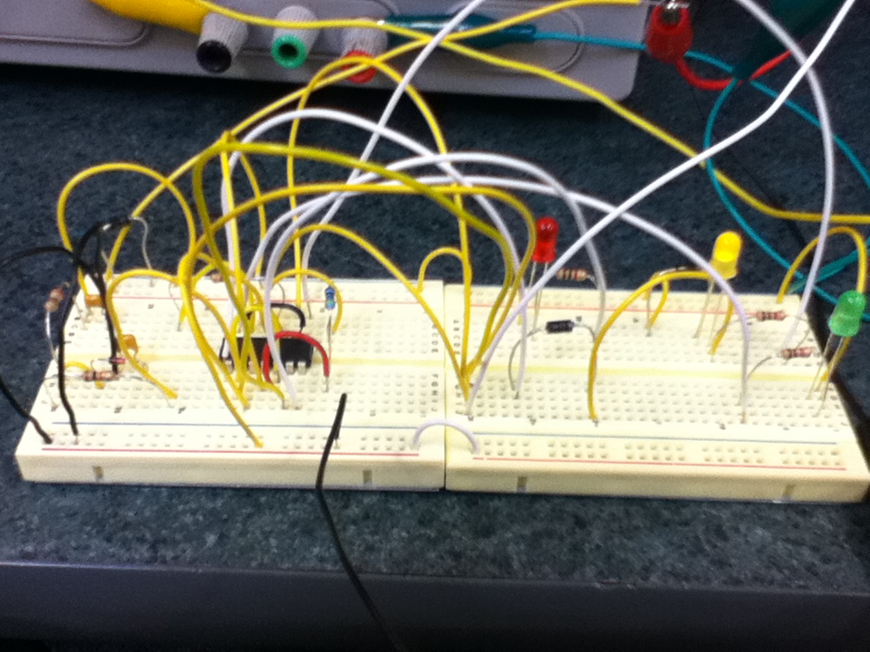
| Diagram of finshed product of oxygen sensor |
No comments:
Post a Comment